Last update: 25/03/2013
All the material present in this page, if not otherwise specified, is covered by the Creative Commons Attribution-Non commercial-ShareAlike license

PROJECT
USB In Circuit Debugger for Microchip MCUs, compatible with serial ICD2
AUTORI
Walter Lain
Massimo Lunardon
FEATURES
- USB connection (RS232 emulation)
- Compatible with Microchip ICD2
- Can be used for in-circuit debugging
- Protection fuse
- Jumper to power the electronics under debug via the USB 5V

This circuit has been adapted from Lothar Stolz design.
The target was to have an economic programmer/debugger for Microchip PIC MCU series, as part of an educational project called
"PIC Programming with Linux".
The basic instrument needed to use PIC MCUs is a programmer. There are a lot of designs available on the internet, and also a lot of
commercial programmers.
If you can settle for programming an MCU by removing it from its circuit and putting it on the programmer socket, with a few euros
(even less than 10) it is possible to build a simple serial or parallel programmer.
If instead removing the MCU from its circuit is inconvenient or impossible, or you need to debug both the software and the hardware together,
more complex circuits are needed, like the ICD manufactured by Microchip itself.
The ICD acronym means In-Circuit Debugger, and in fact this device allows, in addition to simple programming, the execution (for the compatible MCUs)
of the debug on board. This means to be able to check not only that the software is managing the I/Os in the right way, but also wether the circuit around
the MCU is reacting to the signals as it is supposed to or not.
The ICD2 is on sale at Microchip website for about 121€ (7/1/2007), together with a manual, the MPLAB development software (free, available only for the
Windows operating systems and closed source), an USB cable and an ICD cable.
The IDE used for the previous mentioned project, Piklab, is fully capable of using
the ICD2 as a programmer, while the support for the debugging is yet in an early stage.
The cost of the ICD2, while not being so high if compared to other similar tools on the market, can be a bit too much for a simple hobbyist.
Luckily, on the internet it is possible to find some schematics for ICD2 clones, with similar features.
The only difficulty in the assembly is the FTDI circuit that
converts USB to RS232, since it is an SMD component with a 32-pin 0.8mm LQFP package. It would be possible, however, to replace this circuit with a MAX232,
and providing an external 5V power supply the circuit can be used with a serial port (it can't be done on the same pinout, of course).
The total cost, buying all the components from Farnell, will be about
55€, but it is possible to find most of the components in any electronic hardware store for a lower price. The MCU used, a PIC 16F876A, can be required to
Microchip as a free sample.
One of the most important features of this device is that it will be detected as a normal ICD2 even from the MPLAB software, that can also update the internal
firmware if/when needed. In this way it has been possible to obtain an updated release of the firmware (2.7.0, included in MPLAB v7.40, that can be found at the end of this page).
To program the MCU the first time a simple programmer would suffice.
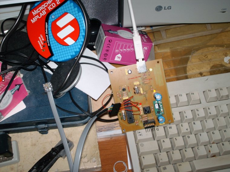
It is also possible, having another ICD2, to connect it directly to the program connector available on the board (in the first prototype this could be done by soldering
the wires on the MCU pins, as can be seen in the image below), and program it on-board. This system has been used also to download the updated firmware after the MPLAB
automatic update.
The FTDI drivers are available on the manufacturer's website
for a large variety of OSes, including Windows, Linux and Mac OS.
In Windows environment keep in mind that the MPLAB doesn't work well with serial ports over COM2 if in between there is a void (if COM2 is not present, MPLAB won't communicate
easily with a device mapped on COM3 or higher ports).
In linux environment, the FT232 chips are recognized since kernel 2.6, without any other driver installed.
To obtain the PCB, you can use a small batch PCB manufacturer such as
Itead or
Seed.
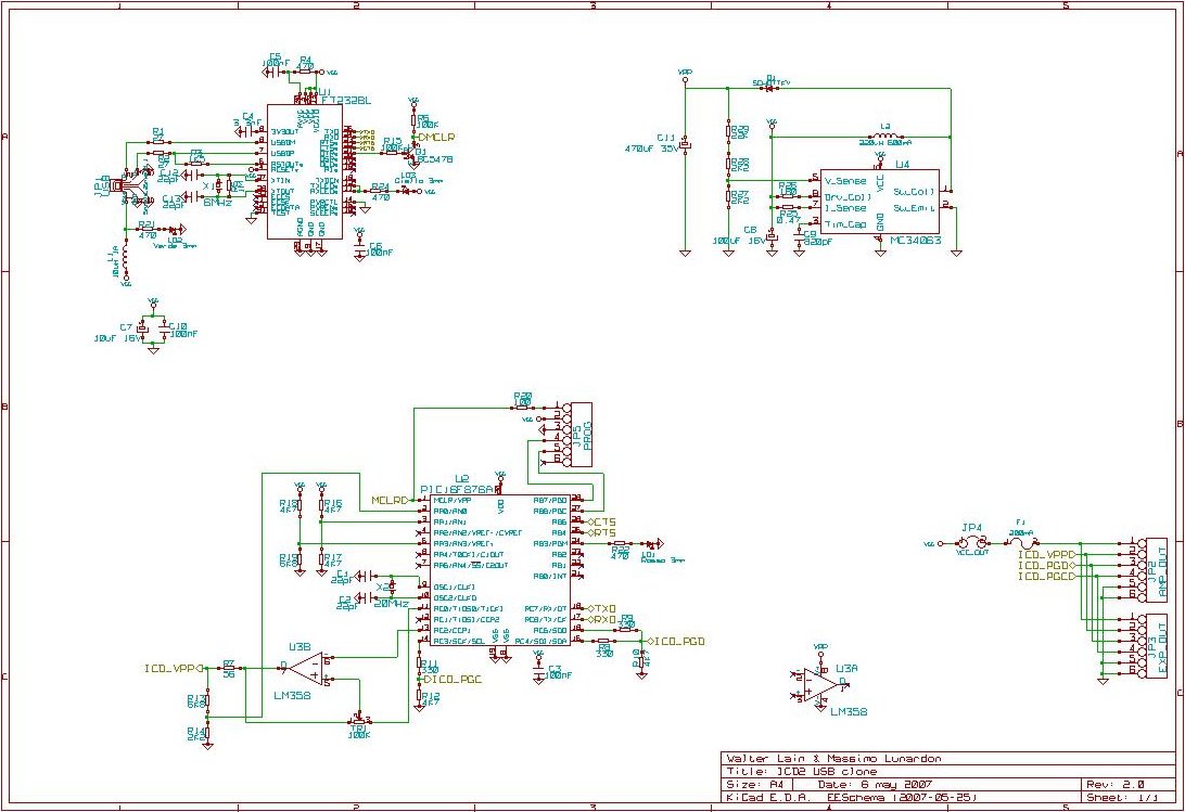
REV 2.0 - Single layer (6/05/2007)
Diagrams and PCB (you will need some Licad libraries
available here.
Firmware
Note: pins 5 and 6 of U3 are swapped in the schematic. They are instead right in the pcb.
PDF documents:
Schematic
Bill of materials
Copper bottom
Copper top (jumpers)
Silkscreen top
Silkscreen bottom
REV 2.3 - Dual layer with RJ11 socket (17/02/2013)
An RJ11 socket with the same pinout as the ICD2 has been added. In this way it is possible to use the standard cable provided with the ICD2.
The circuit has also been shrinked a bit and converted do dual layer.
Kicad project and PDF documents
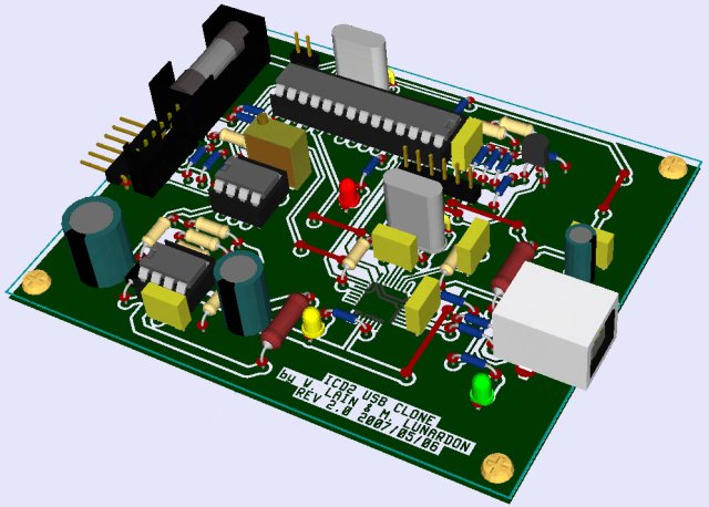 3D view of the r2.0 board
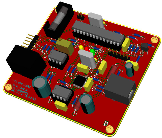 3D view of the r2.3 board
The authors assume no responsibility for any damages of any kind that may be caused by the use of the material here presented.
Impaginazione by KCS'81